Build Your Own Steno Keyboard: It’s Easier Than You Think
If you’re interested in learning stenography, and you’re not sure what keyboard or stenotype machine to invest in, here you’ll find details about what’s involved in assembling a suitable mechanical keyboard. I hope this helps you decide if this is a good option for you. Spoiler alert: piecing together a keyboard might be easier than you think. (It might also be harder than you think; you have different experience to me.)
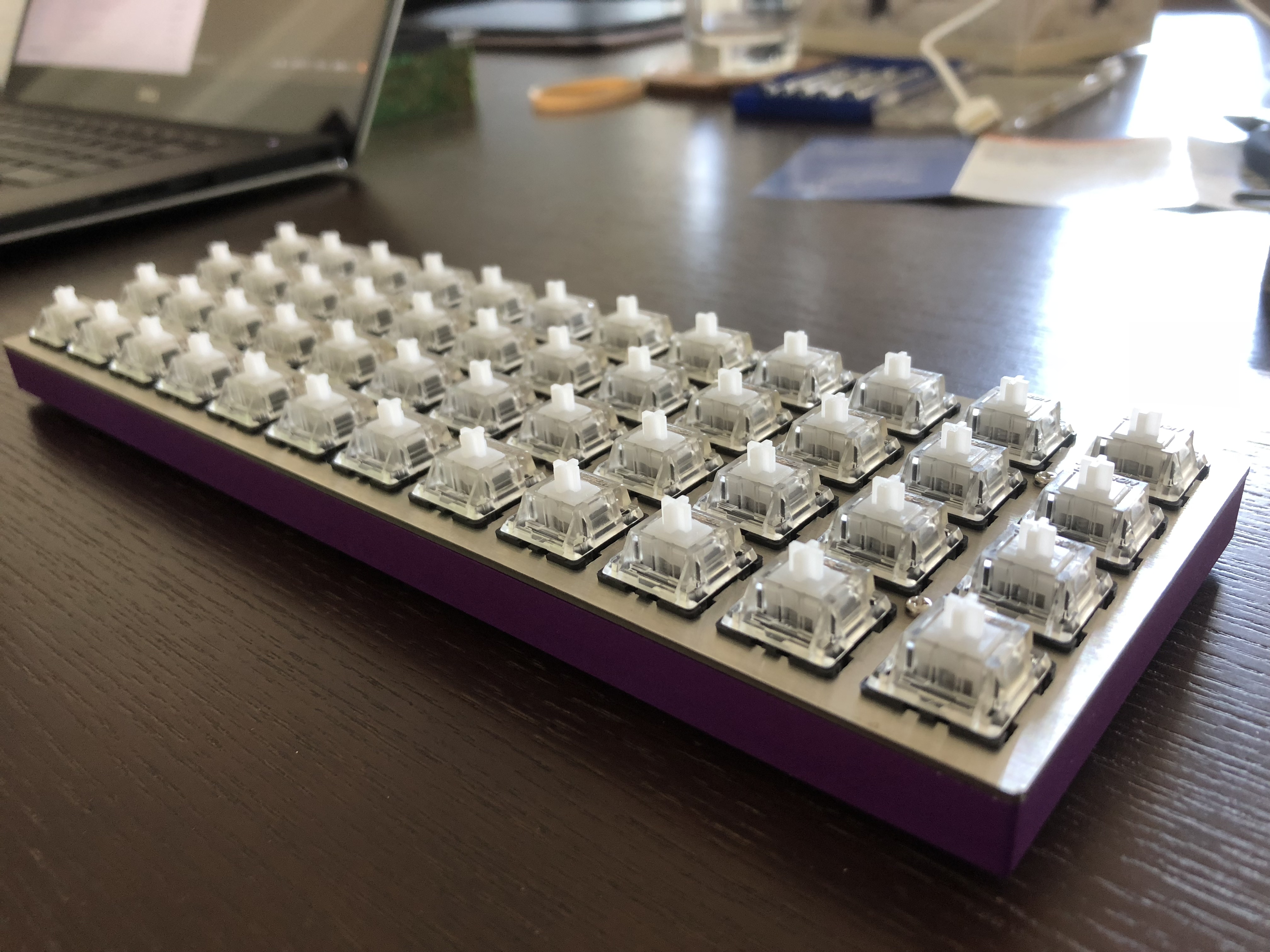
Planck keyboard for stenography
When I decided to switch from QWERTY to stenography, my immediate barrier to getting started was finding a device I could write on. The Open Steno Project suggests you can buy a compatible keyboard for as little as $26 (USD). Shipping to Australia, however, is expensive. In the beginning, there was a lot of information for me to process to figure out what option would be the best for me, and I knew nothing about hardware or electronics. I ended up buying an UTOPEN Stenoboard pre-made, which now appears to be out of production. It was a suitable device to train on with a nice split layout, but the keys were tough on my fragile wrists. Later, I learned a little more and ended up building my own Planck keyboard to use for stenography. It was vastly easier than I had expected, so I wanted to share the details here, so you can build one too.
Why use a Planck
The Planck keyboard is a compact device (40% keyboard!) that balances light key switches (35 cN, which is as light as it gets for Cherry MX style mechanical keyboard switches, but still require more force than stenotype machines) with reasonable prices (far cheaper than stenotype machines that start at a grand). It’s an NKRO keyboard, which means you can press as many keys together at the same time as you need for steno. You can use it as a regular keyboard too, if you want. The Planck also requires a small amount of assembly and a little bit of knowledge of computers. If you’re eager and persistent, it’s straightforward to do.
Without a split layout, the size of this keyboard might be too small for some people’s frame.
What do you need
- Keyboard parts (bought online)
- Firmware (with a little knowledge of computer command lines)
- Plover software (downloaded for free)

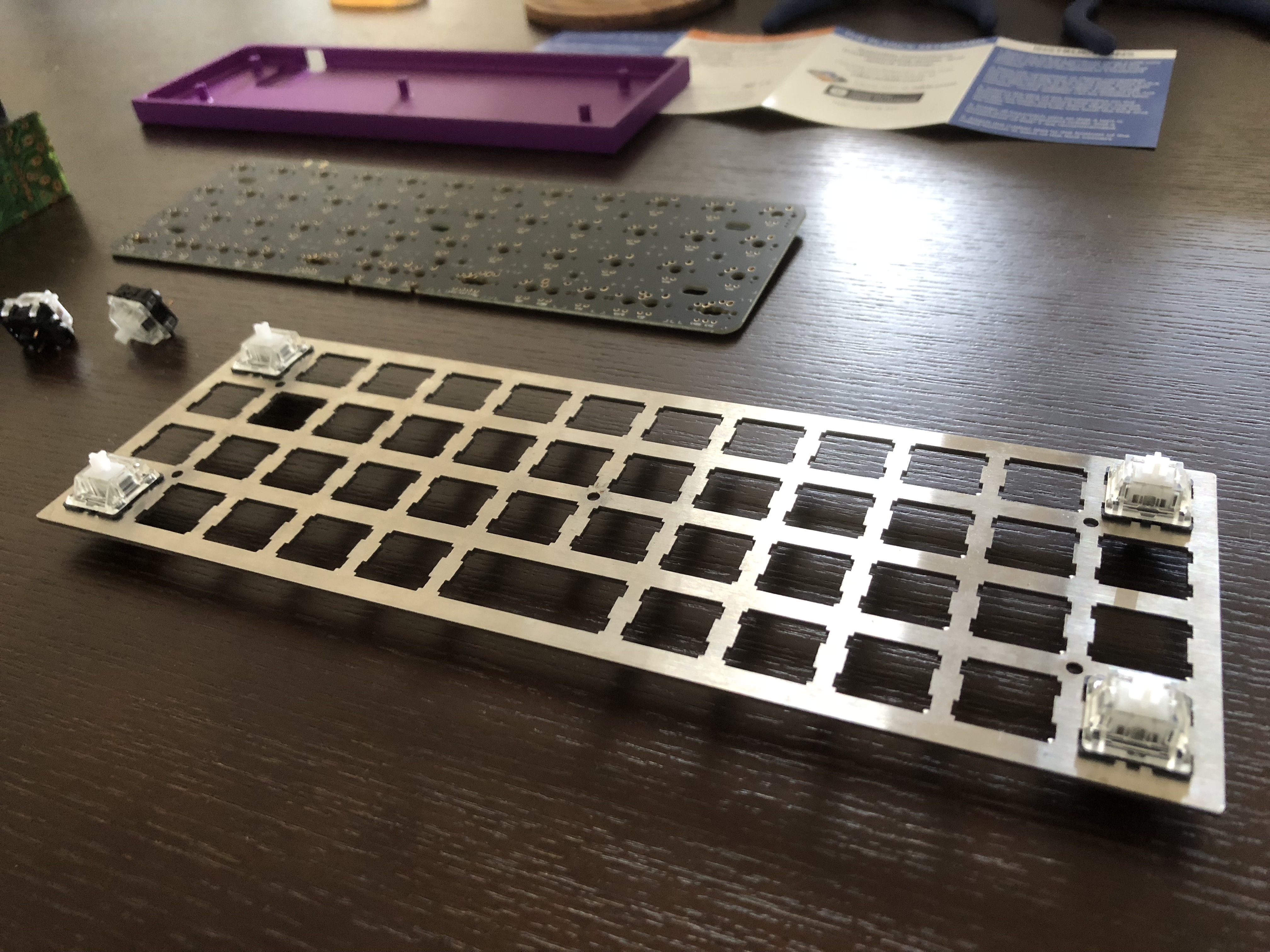
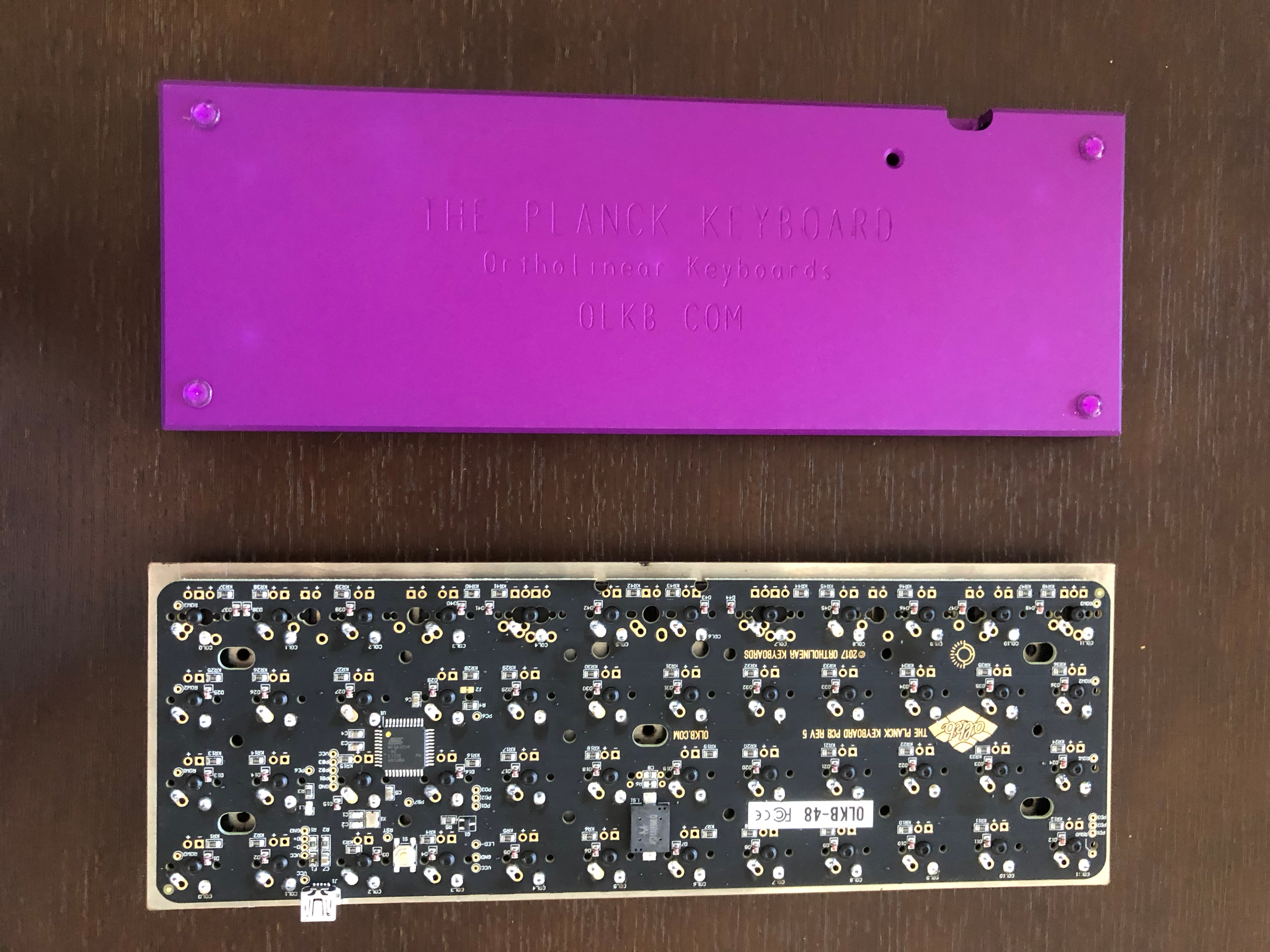
All the keyboard parts
There are a few main parts of a keyboard you need. The milled bottom of the keyboard is the purple part shown in the bottom–left above, which is used as the base of the keyboard to hold it all together. On top of this will sit the PCB (Printed Circuit Board), which is the part that makes the keyboard operate like a keyboard, shown in the left of the photo above. On top of the PCB will rest the top plate, which is used to hold the key switches in alignment with the PCB and protect the PCB, shown in the bottom–right of the photo. In the top plate will sit the key switches, which are the mechanical part that let your keys move up and down when you press them, shown in the top–left of the photo. You won’t, however, assemble the keyboard in this order. When the pieces are all attached, you’ll see that the pins or legs of the key switches will pass through the gaps in the top plate and the holes in the PCB and soldered to the PCB.
You’ll fasten together your keyboard in five places using screws, shown in the top of the photo, and attach the four plastic, sticky feet to the base of the keyboard, which is the tiny grid of plastic circles in the photo, so your keyboard doesn’t scratch your desk. Finally, the key caps are placed on top of the switches, shown in the top–right of the photo, so that it looks like a real keyboard. For steno, they’re flat keys that have close, adjacent edges so that it’s easy to press 2 together at the same time. There’s also a sticker. You don’t need that to build a keyboard.
Here’s the shopping list:
- Keyboard parts you can order online:
- The Planck parts from OLKB:
- Milled bottom for ~AU$67.57 (50 USD).
- PCB (Printed circuit board) for ~AU$54.06 (40 USD).
- Top plate (Stainless steel, MX switches) for ~AU$20.27 (15 USD).
- 48 Gateron MX Clear plate mount switches:
- 1 pack (61 piece) switches from eBay for ~AU$33.08 (24.50 USD).
- 48 G20 key caps from PMK:
- 5 × G20 1u pack 10 for ~AU$13.52 (10.00 USD).
- A USB mini cable for AU$10.75 (~7.95 USD) from any consumer tech store or for $5 on eBay.
- The Planck parts from OLKB:
- A soldering iron for AU$19.82+ (~14.66 USD), or you might borrow one.
- Solder wire. In particular, solder for hobbyist electronics projects, such as rosen or resin flux core (just ask at the store for one of these).
- Some spare parts to practice soldering, such as switches, legs, and a board. This is only to build your confidence, not strictly needed.
- Tiny Phillips head screwdriver to screw in screws.
- Tiny pliers to straighten pins (if needed).
- Keycap puller to rearrange keys (you could improvise without a keycap puller if you had to).
All together it costs about AU$219 or ~162 USD, including soldering iron and USB mini cable, which you might borrow or already have.
Steps
Practice
Note: Before starting this project, I had never soldered anything. If you haven’t either, check out Soldering 101.
Practice soldering unwanted legs of any electronics to an unwanted board, if available, and practice soldering the legs of unwanted switches, if available (particularly if you have spare, bent ones).
Preparation
Check that you have everything you need handy, including your soldering iron and screwdriver, on a surface that could sustain some nicks and scratches.
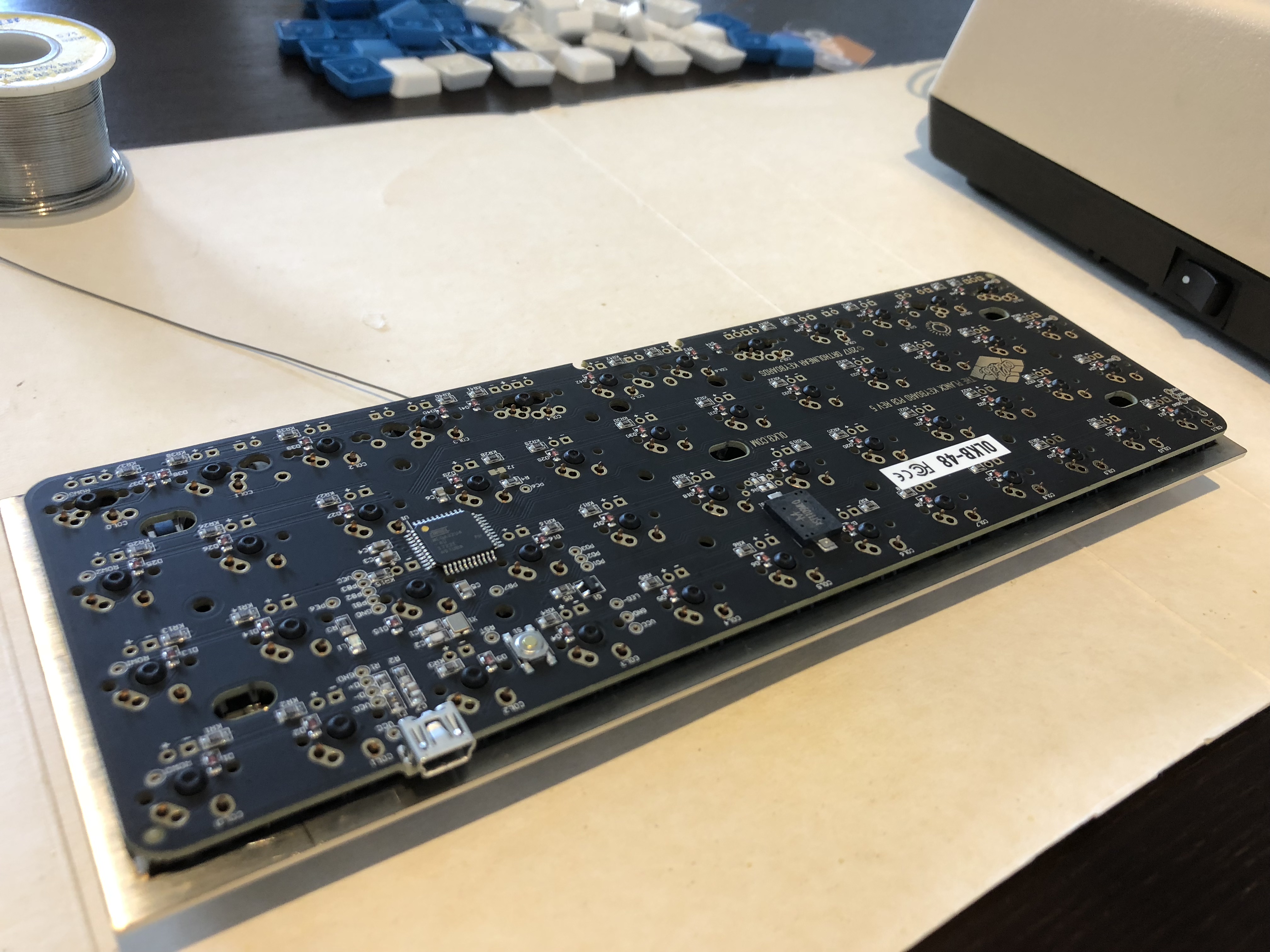
Connect the USB mini cable to the PCB and your computer: if all is well, it will chirp and light up (note: handle it carefully and don’t put the PCB on any conductive surfaces e.g. metal). Once you’re happy, disconnect the cable.

USB-connected PCB
Check that the pins of all the switches are straight. Straighten any crooked ones with pliers. Skip any particularly bent switches completely and use others. Make sure you have enough to fill the board.
Build your keyboard
Time for action!
Stack switches, top plate, and PCB
Find the nicely laser-cut side of the top plate. Place the key switches in top plate and PCB at the same time, starting at the corners, with pins aligned to PCB holes. Push them in until they click into place. To give you an idea of how to do this:
- Position the PCB board with its branding and microcontroller side up.
- Align the PCB to the milled bottom so the USB port is at the top (but you don’t need to attach the milled bottom yet).
- Hold the PCB and top plate together in the air at the edges while placing the key switches in.
Key switches in top plate
Solder
Heat your soldering iron to 315℃ or 600℉.
Flip the top plate, PCB, and switches over.
Flipped top plate, PCB, and switches
Solder the pins to form “tents” of solder around them. Important notes:
- Make sure the solder falls into the holes and fills them properly to form a proper connection.
- Be careful around the microcontroller to avoid spilling solder.
From OLKB’s website:
When soldering each pin, it’s best to place the tip of the iron on the pin/pad and push the solder into the intersection of the two. Getting them hot helps the solder to form a good connection. Try not to get solder anywhere but on the gold pad, and be sure not to form any bridges with nearby components. Doing so may cause random key presses or break things (temporarily, likely).
The size of the solder you’re using is mostly unimportant, but it’s recommended that you use a smaller gauge (smaller in diameter), as it will be easier to control the flow. It is recommended that the solder be rosin/flux cored to help it flow onto the pads. Additional flux may be used, but shouldn’t be needed.
You’ll be soldering 2 pins for each keyswitch, and 2 pins on the LEDs/SIPs, if you’re installing those.
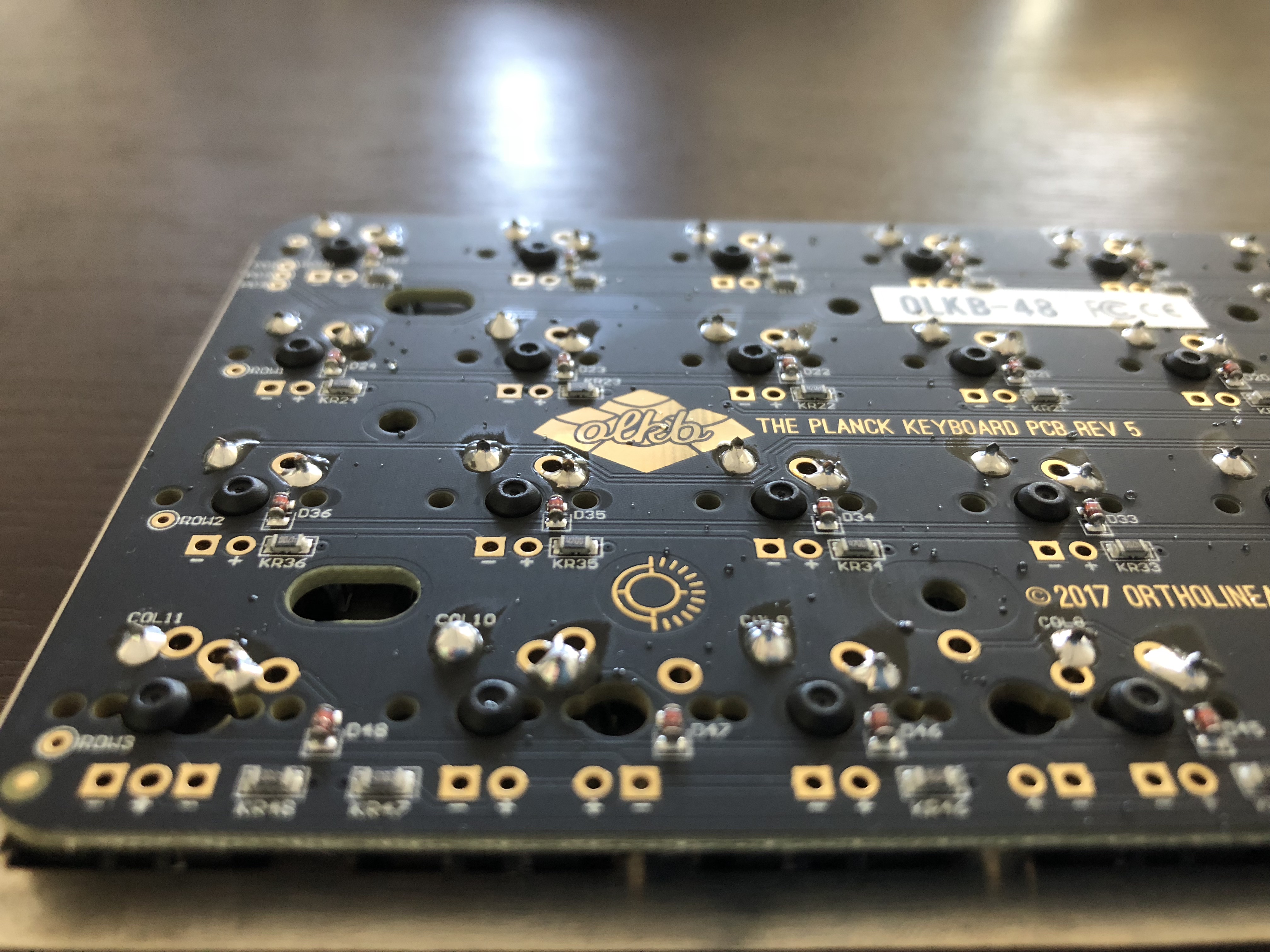
PCB (Printed circuit board) with soldered key switch pins resting in the top plate
Test your keyboard so far
Plug in your new keyboard again using the USB mini cable and type with every key to test that every key works properly: try using Keyboard Tester. Some modifier keys like Shift or the Raise and Lower key won’t do anything unless you press another key too.
Key switches in top plate
Fasten the milled bottom
Attach rubber feet to the bottom of the milled bottom (the base) in the corners.
Milled bottom
Place the keyboard (top plate, PCB, and switches) in the milled bottom, tilting the USB port side first so it fits through the gap available for the USB port.
Top plate, PCB, and switches alongside milled bottom with feet
Use a tiny screwdriver to fasten the screws to hold it all together.
Add your key caps
Add key caps to keyboard. Handy notes:
- First, arrange key caps to your desired layout near your keyboard.
- Add the key caps to switches. Push them hard onto the switches.
- Use a key cap puller to rearrange keys (if needed).
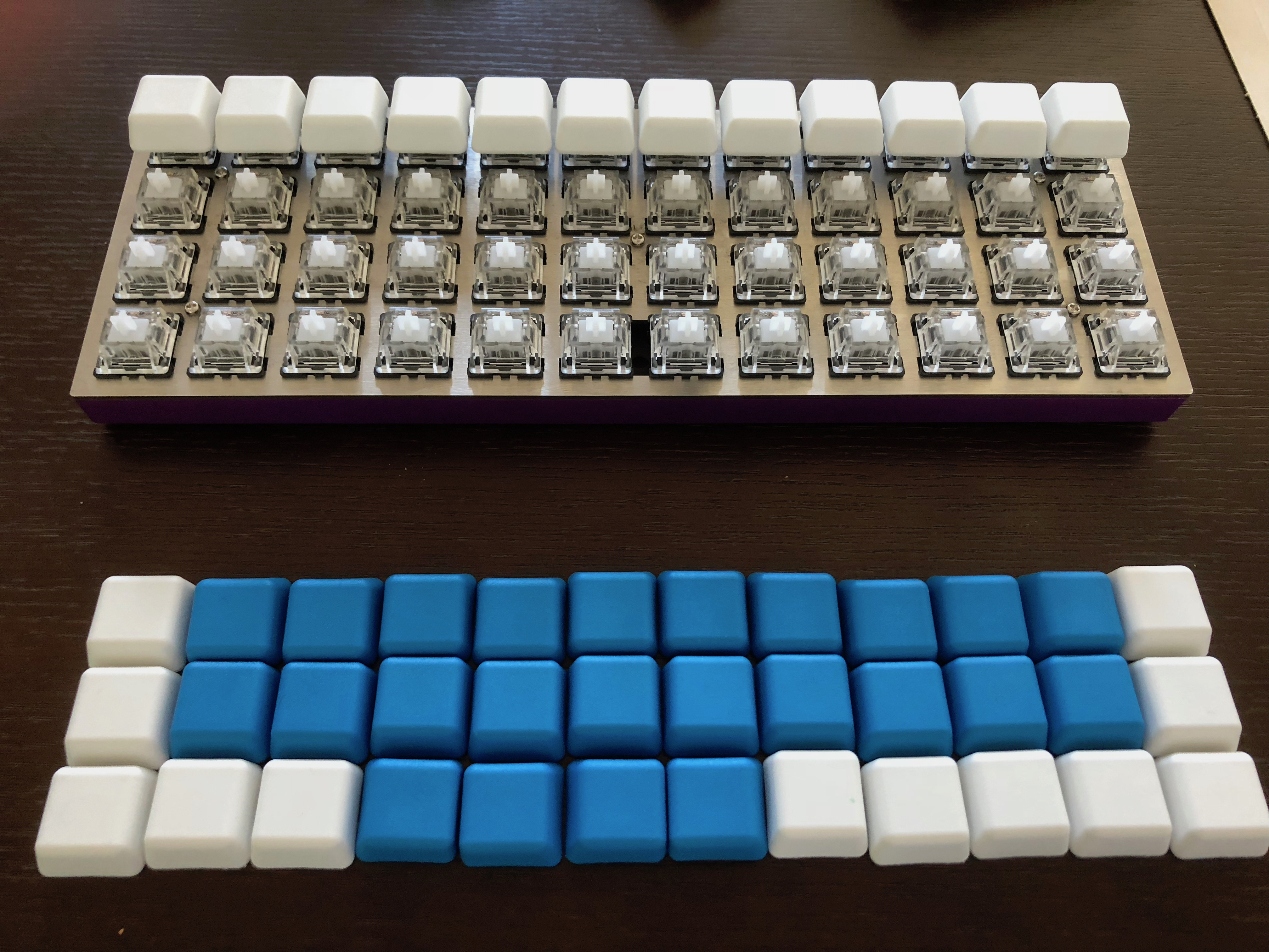
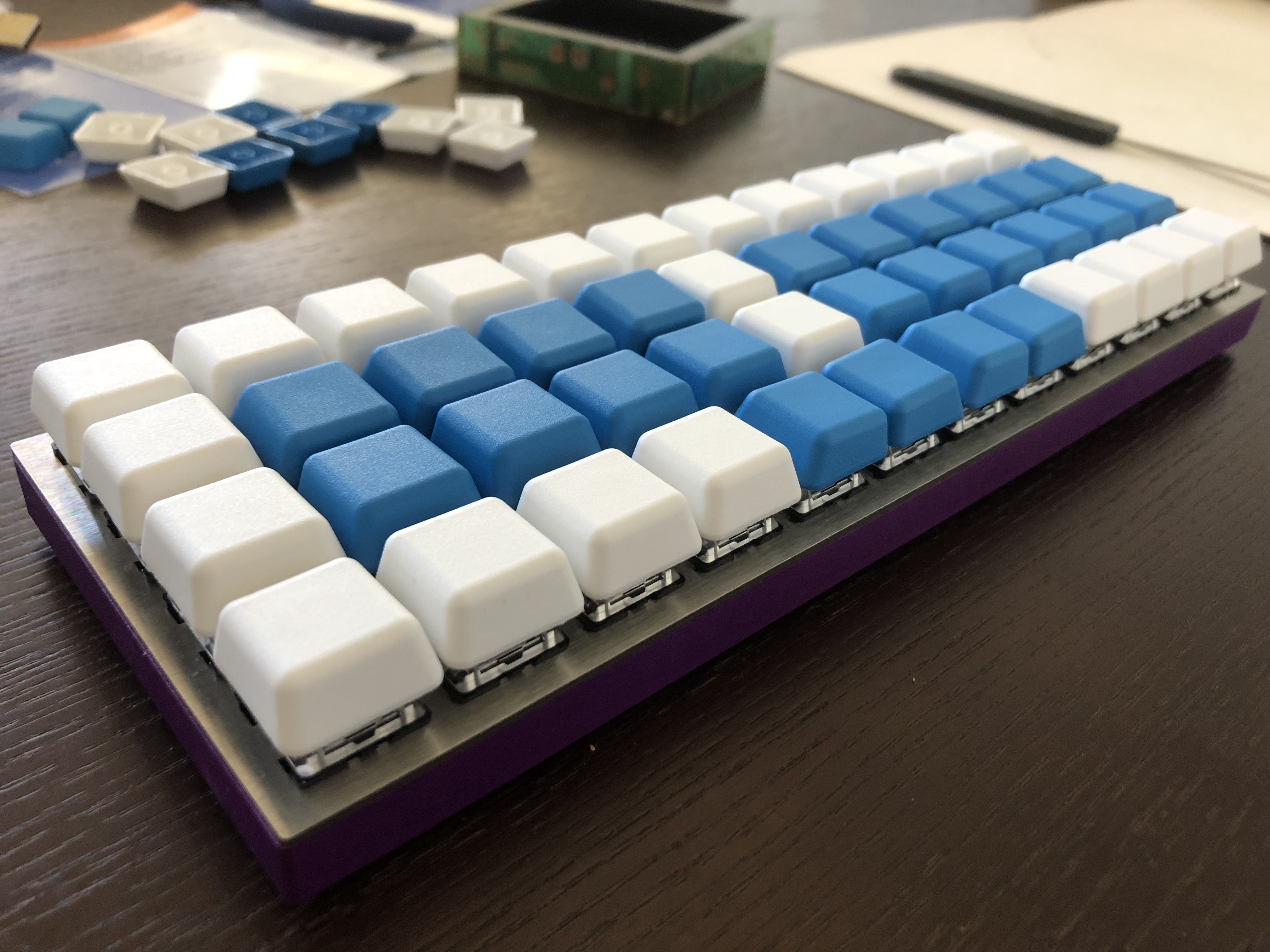
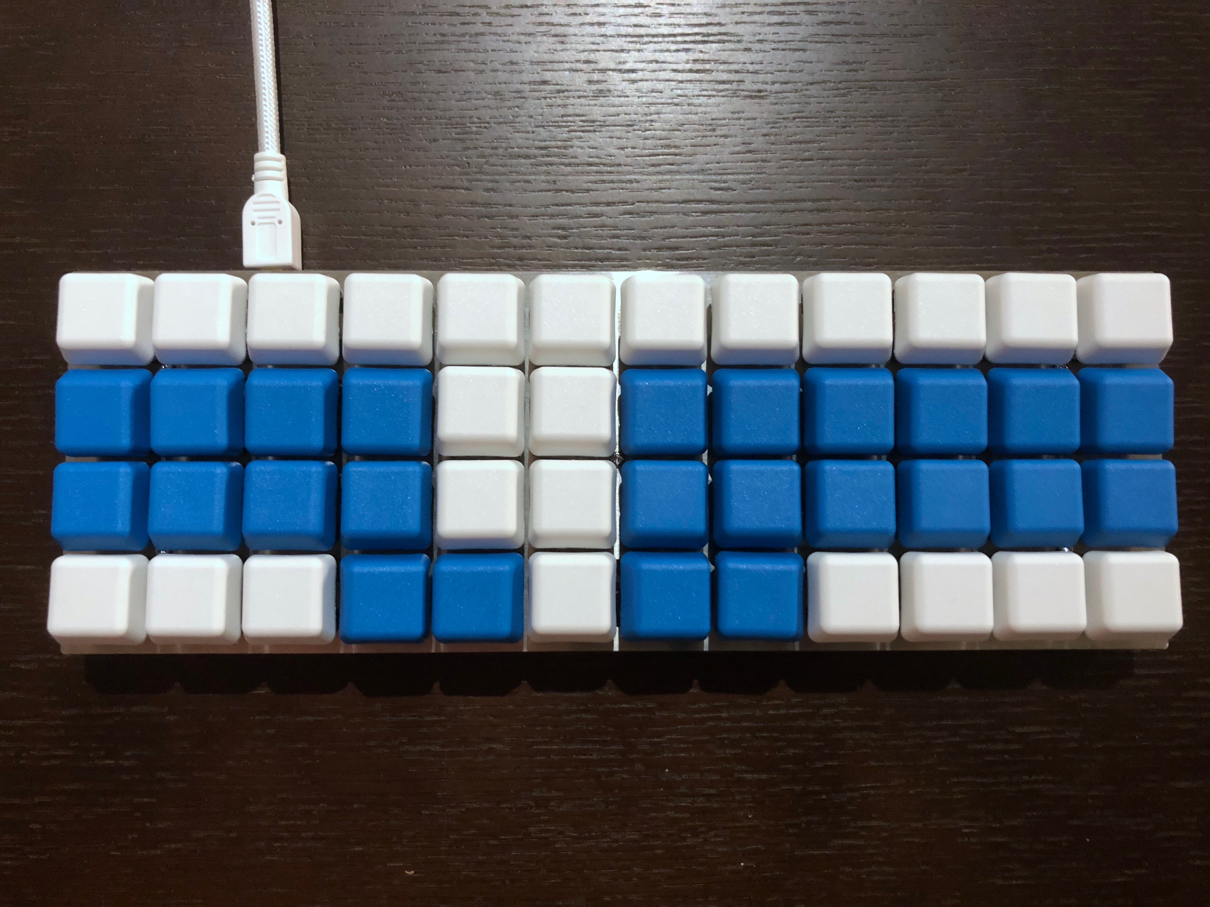
Arranged G20 key caps with number bar keys attached to the keyboard
I’ve used blue key caps for the consonants and vowels of the steno layout. You can see in the pictures that I started with them snugly laid out together in the center of the board, then re-arranged them to the outer edges of the available keys on the board (the key puller came in handy here). This is to minimise how cramped the Planck can feel if your hands are too close together. Now it is much more comfortable.
It’s also worth noting the orientation of the key caps. While flat, the key caps have a slight tilt, which I’ve arranged so that any keys that are supposed to be pressed together are tilted toward each other. Notably the AO and EU vowel keys are sideways while the DZ keys, for example, are up and down.
Your keyboard is complete!
Planck steno keyboard with updated layout
Install firmware
This next part gets a bit hairy if you’re not familiar with coding. If you’re new to code, you might want to read up on using the command line and learn enough command line to be dangerous.
If your new keyboard doesn’t behave quite right, such as the NKRO setting, or you want to change the layout, you’ll need to install the firmware so you can change the keyboard layout:
- Download the whole firmware project from https://github.com/qmk/qmk_firmware,
- See QMK Plank overview and Planck getting started pages.
- Save the firmware folder somewhere like
~/projects/qmk_firmware/.
- Duplicate the The Default Planck Layout folder, which looks like this:
keyboards/planck/keymaps/default/and edit the copy as you please, such as to enablenkroor move the consonant keys to the outer edges. You should have aconfig.hfile, akeymap.cfile, and arules.mk. You can see my layout on GitHub. - Change directory (using
cd) into the root directory where you saved the firmware e.g.~/projects/qmk_firmware. - Enter
make planck/rev4:YOUR_LAYOUT_NAME_HEREwith the correctrevnumber for your Planck device. (At the time of writing, the latest looks likerev6.) This builds the firmware. - Plug in your new keyboard and on it press the key combination for “Reset”:
- The reset key combination is: 5th key/thumb in from both bottom corners for
Raise+Lower, and second key across from top–left corner on the top row.
- The reset key combination is: 5th key/thumb in from both bottom corners for
- Enter
make planck/rev4:YOUR_LAYOUT_NAME_HERE:dfuwith the correctrevnumber for your Planck device (as above) and the additional text:dfuto program the Planck.
Plover
Jump over to the Plover website to grab the software you need to steno on your new keyboard.
- Switch your new Planck keyboard to the Plover “layer” using
Raise+Lower, which is the 5th key/thumb in from both bottom corners, as well as the Plover key, which is the second down and second across from top–right corner. It should chirp successfully! - Turn on Plover.
- Steno!
Share your adventure
The Plover, mechanical keyboard and OLKB communities get pretty excited about these kinds of DIY projects. We’d love to hear about your keyboard, so feel free to share, or otherwise ask lots of questions.
I hope this helps you with your steno, keyboards, and typing adventures.
To practice stenography, I designed and built an app for steno typing drills. To learn more about steno, check out Typey Type for Stenographers.